Neutron - Overlay Networking for OpenStack
Neutron is an OpenStack project to provide “networking as a service” between interface devices (e.g., vNICs) managed by other Openstack services (e.g., nova).
Starting in the Folsom release, Neutron is a core and supported part of the OpenStack platform.
Examining Project Network Topology
Navigate to Network -> Network Topology using the second level navigation tabs.
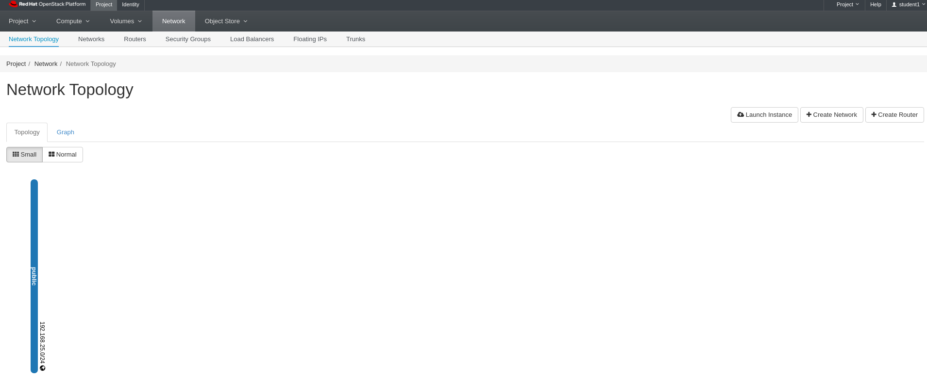
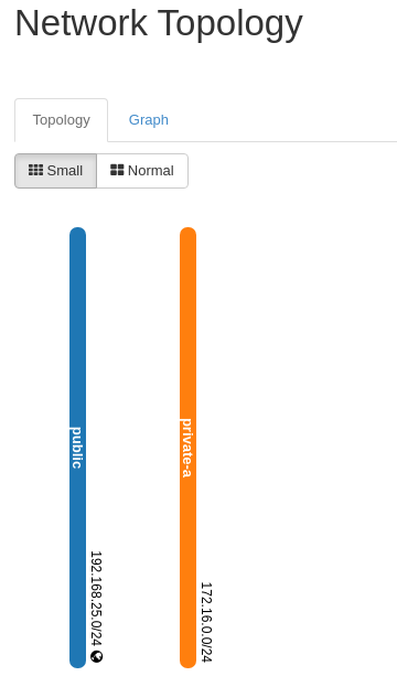
Lab 2 Figure 1: Neutron Network Topology
There are two ways to view the project network layout.
- Topology which is more of a logical network layout
- Graph which is fun becuase you can drag it and things bounce around :)
You will notice that at this point, there is only 1 network named public. This is an external network that the instructor added as an OpenStack administrator. The public network is shared among all projects and will be utilized in the next lab for managing floating IP addresses. As a project member only, you will not have the ability to modify the public network.
Let’s Create our First Project Network
Click on the Create Network button in the upper right
Enter private-a as the Network Name
Leave Enable Admin State and Create Subnet checked and click Next
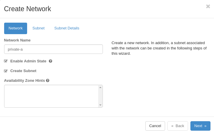
Lab 2 Figure 2: Create Neutron Network
Next We Will Create a Subnet
Enter private-a-subnet as the Subnet Name
Enter 172.16.0.0/24 as Network Address
Leave IPV4 as the IP Version
Leave Gateway IP blank and make sure Disable Gateway is not checked
Click Next
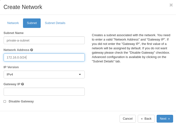
Lab 2 Figure 3: Create Neutron Subnet
In order to differentiate visually from the public network’s IP space, we will use 172.16 for the first 2 octets in the IP space for our private project networks. This way it is very easy to tell them apart from the public network.
Be aware that because these project networks are VXLAN tunnels, they can be any IP space you desire and there will not be conflicts in the cloud.
Lastly We Will Enter the Details for the Subnet
Leave Enable DHCP checked
Leave Allocation Pools empty (we’ll use the entire range)
Enter 192.168.0.4 in DNS Name Servers
Leave Host Routes empty and click Create
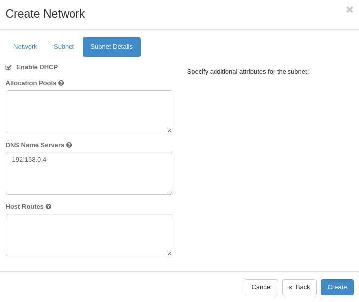
Lab 2 Figure 4: Enter Neutron Subnet Details
You should see a green success box in the upper right corner of the screen that says Success: Created network “private-a”. Your network topology should now show 2 networks, public and private-a
Note that the success and error messages in Horizon only show briefly and then they disappear.
If this is not the case, let the instructor know now
Lab 2 Figure 5: Neutron Network Topology Showing New Network private-a
Let’s Tie these 2 Networks Together with a Neutron Router for Layer 3 Communication
It is nice that we have these two isolated networks. However, when we add machines to the private-a network, we will want them to get out to get updates, retrieve data, etc.
In order to allow this to happen, we need to create a Neutron router.
Create a Neutron Router
Click on the Create Router button in the upper right
Enter router-public as the Router Name
Leave Admin State equal to UP Select public network for External Network and click Create Router
Note that you may need to scroll down to see the public network in the External Network drop down.
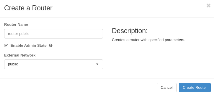
Lab 2 Figure 6: Create Neutron Router
You should see a green success box in the upper right corner of the screen that says Success: Router router-public was successfully created. Your network topology should now show 2 networks, public and private-a and 1 router connected to the public network.
If this is not the case, let the instructor know now
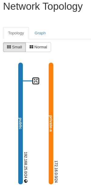
Lab 2 Figure 7: Neutron Network Topology Showing New Router router-public
Lastly Let’s Add an Interface for the private-a Network to router-public
Hover your mouse over the router in the network topology You should see a box pop up with information about the router Click Add Interface
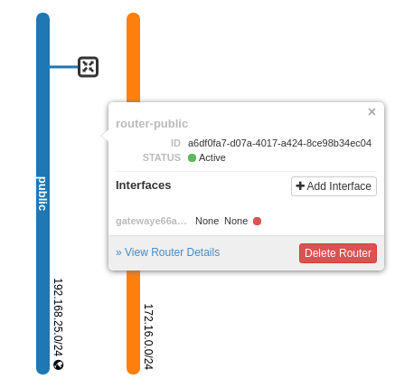
Lab 2 Figure 8: Router Information Box with Add Interface Button
Select private-a as the Subnet
Leave IP Address blank and click Submit
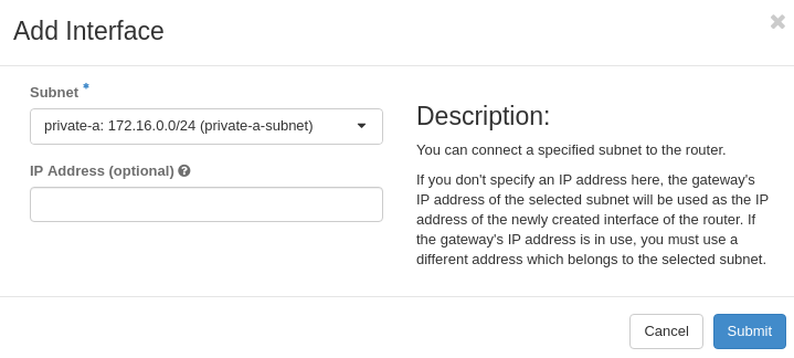
Lab 2 Figure 9: Add Interface Options
You should see a green success box in the upper right corner of the screen that says Success: Interface added 172.16.0.1
You will be taken to router-public’s overview screen.
If you navigate back to our network topology, it should now show 2 networks, public and private-a and 1 router connected to both the public and private-a networks.
If this is not the case, let the instructor know now
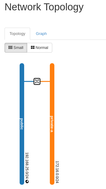
Lab 2 Figure 10: Neutron Network Topology Showing router-public Attached to Both Networks
Summary
You should now have 2 networks in your project.
The first is the external network named public. The second is a private VXLAN network named private-a.
We then created a Neutron router to tie both of these networks together so that instances on private-a may route externally for updates, data, etc.
Also, we will now be able to associate floating IP addresses from the public network to instances on our private-a network.
In our next lab, we will start working with floating IP addresses.
Workshop Details
| Domain |
|
|
| Student ID | ||